It has been a while, but don’t worry, my students have been giving me plenty of blank stares in the meantime. Seriously, I am teaching a course this semester called Design of Machine Elements which I consider a key opportunity for students to bridge their engineering knowledge toward their upcoming professional career. Given the course is an elective, I have opted to not give exams, but instead assign regular engineering project problems. We discuss fasteners, bonding, shafts, gears, springs, etc. and discuss critical implications of fit, tolerancing, and perhaps most importantly the different means of engineering communication. At the heart of every single problem, are load and deformation analyses. These analyses are much easier for well characterized, isotropic materials (e.g. steel, aluminum, cast iron), but become much more intensive as we change to a highly engineered, anisotropic material such as a carbon fiber reinforced epoxy.
As we have discussed in the past, understanding and visualizing deformation using DIC allows us to see what is happening in our world. While measuring what is happening in the real world is ideal, it is costly and time consuming, so we must rely on analytical modeling. The key to these models is that they must be rooted and match the real world which may sound easy, but is far from it. I can feel Carl rolling his eyes as he thinks I am reaching for my soapbox, but I will refrain and instead promise to post an editorial on this important topic in the future. In my next post, we will continue to discuss modeling and why it is so difficult to model composite structures predictively. Before I do though, you may note that I normally include references throughout my discussions, but in this case since there are many texts that cover this topic I am using my class notes. Should you like more information, a well-written reference solely on this topic has been written by my friend and colleague Dr. Alan Nettles.
One of the main ways that we perform these analyses with anisotropic materials is to implement classical lamination theory which allows for determination of the forces and moments of a laminate. There are several assumptions that must be made. First, each layer is made of material with uniformly parallel, continuous fiber even each layer is different thickness or material. Next, the stresses and strains in the through-the-thickness direction is ignored and the thickness is much smaller than the length and width dimensions. Finally, it is assumed that perfect bonding exists between the layers and between the fibers and matrix materials. While the thickness assumptions are easily shown to be reasonable by the negligible effects through-the-thickness, uniformity and perfect bonding are difficult to realize. We do the best we can by using proven, robust manufacturing methods backed up with a solid quality plan which are all topics for another day.
We get started with laminated plate theory by first determining the stiffness in each direction for each individual layer and then use a coordinate transformation to adjust these properties to account for the layer fiber orientation in the global, laminate orientation. Recall for our previous discussion that since we are working with an anisotropic material in a tube as we change the fiber direction for each layer, we must adjust the properties of that layer with respect to the overall laminate orientation. Next, we determine the distance of the top and bottom of each ply with respect to the midplane of the laminate. If each layer is analogous to the flanges of an I-beam, increasing the distance between the flanges will result in a stiffer beam.
Once we have all of this information for the individual layers, we can then compile the information to calculate the ABD matrices. These are showing in Figure 1:

Figure 1: The method of determined forces and moments from strains and curvatures using the ABD matrices.
The A matrix (upper left quadrant) is called the extensional stiffness matrix and relates normal stresses and strains. The D matrix (lower right quadrant) is call the bending stiffness matrix and similarly relates the curvatures with bending moments. Both of these matrices contain many terms noted to be the isotropic material response and are all that characterize an isotropic material. However, each has additional terms for shear-extension or bend-twist coupling which are visualized in Figure 2. The B matrix is the other two remaining quadrants and is a complex mix of coupled stiffnesses including bend-extension, bend-shear, twist-extension, and shear-extension.
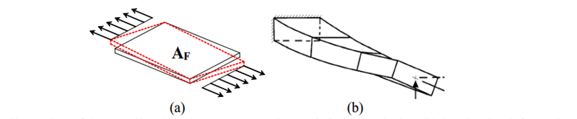
Figure 2: Shear-extension (a) and bend-twist (b) coupling.
It is critical to note that if the laminate is symmetric about the midplane, the entire B matrix is zero. Similarly, non-ISO terms for the A matrix are zero if the laminate is balanced meaning each off-axis layer has a corresponding normal (rotated 90 degrees) layer. We can further simplify and get to only ISO terms if we build a laminate to be quasi-isotropic such that the non-ISO D matrix terms all approach zero. These methods are commonplace, especially when replacing metals, and make the analysis much easier. Many argue that using these simplifications results in a reduced realization of the material capabilities which is yet another topic for another day.
Now that the ABD matrices have been found, the global stresses and strains can be calculated and then converted back to the local orientation for each layer. These are then commonly used to figure out layer-by-layer where the likely failure points are located using first-ply failure or other failure methodology. While this process is somewhat easily described here, it is computationally intensive for a human, thus most companies have spreadsheets or code to facilitate these analyses.
As always, I look forward to any questions and comments; we have definitely skimmed over a lot of information in this post. After teaching composites last year, I have decided that next time I am going to have the students each generate their own code to calculate laminate response. For perspective, it will take them most of the semester and I am sure they will continue to stare blankly back at me through it all.