So we left off last time discussing anisotropy; specifically how a composite tube may differ from a metal tube. We have defined anisotropy as having different properties or responses in different directions. It would be helpful if anisotropy were easy to visualize, but it is not. Go perform an image search using “anisotropic material” and you may expect to see some nice images of anisotropy [1]. However, the search yields many images that when thought about and combined in various ways allow us to develop an understanding of anisotropy, but none clearly show anisotropy.
Breaking it down into smaller bits can make it somewhat easier to understand. Getting down to the grain size (think 500x magnification), the grains are directional meaning there is crystallographic anisotropy [2]. This is true of most metals (Figure 1), including those drawn into tubes, but the randomness of the grain orientations and the processing method result in isotropy on the macro-scale. What this really means is that the metal tube from our example is manufactured, the grains shown in the both sections of Figure 1 are all oriented randomly. Thus, when they are all put together on the larger scale the combination of all of these randomly oriented grains results in the same properties in all directions; hence, isotropy.

Figure 1: Microstructure of the Ti-6Al-7Nb alloy (500x) [3].
Composites are much the same way at the micro-scale, though they tend to be a bit more ordered. Fibers themselves may either be isotropic or anisotropic depending on the fiber type, while most resins are considered to isotropic. Remember that for both fiber and matrix, we are assuming idealization (e.g. material uniformity, etc.). The big difference then comes down to that as we increase from micro to macro with composites, they remain highly ordered and the randomness that leads metals to become isotropic does not exist. Instead, the highly ordered fiber direction allows us to engineer our manufactured tube to do different things such as be stiff in bending or strong in torsion.
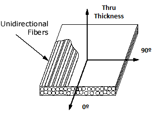
The order comes from the fact that the fibers are oriented in a specific direction and as we go from the micro to the macro we go from considering individual fibers to tows. Consider for a moment Hexcel’s AS4 carbon fiber, which has a tensile modulus of 231 GPa (33.5 Msi) [4]. This fiber has a long history of being used with the 3501-6 Epoxy Matrix that has a tensile modulus of 4.24 GPa (0.615 Msi) [5]. Aside from all of the extremely useful information in reference [5], data from composite properties are also given. For example, the 0° Tensile Modulus (Figure 2) is suggested to be 141 GPa (20.5 Msi) which intuitively makes sense as this value is in between the modulus value of the fiber and epoxy. More precisely, if we consider the fiber volume suggested, 62%, and use the Rule of Mixtures to estimate the composite modulus it comes out to 145 GPa (20.8 Msi) [6]. As suggested by this example, the Rule of Mixtures is reasonably accurate and is commonly used for the 0° (fiber) direction. Estimating other properties and/or strength are topics for another day.

Figure 2: Representation of composite where the fiber direction is shown in the 0° and the transverse is shown as 90°.
Let’s take a step back and remember that we are interested today in identifying the anisotropy of composites which means we should see a different response when we consider the fiber and transverse directions (0° and 90°, respectively). Notice that the data sheet in [5] does not include any 90° properties and while these data can be harder to find, they do exist [7]. Consider the modulus and strength data provided, which is shown in Figure 3, and it is clear that both material properties drop significantly from 0° to 90° orientation. Thus, the response in the 90°, or transverse, direction will be much different because both the strength and stiffness are much lower. It is difference that helps us quantify the amount of anisotropy of typical carbon/epoxy composites.
Figure 3: Mechanical performance of TRS50 carbon fiber with NB301 resin[7].
Now comes the hard part, how do we use these data when designing a composite structure? It is not trivial, it requires us to make several assumptions usually involving material symmetries. For example, we usually say that the properties in the transverse and thru-thickness directions in Figure 2 are almost the same. We call this transverse isotropy which allows us to represent the anisotropy more easily and we can focus on building our composite tube with the specific use in mind which we will do next by taking a look into laminated plate theory.
Thanks for reading and please do not hesitate to ask questions!
References
- Anisotropic Material Google Search.
- Franz Roters, Philip Eisenlohr, Thomas R. Bieler, and Dierk Raabe, Crystal Plasticity Finite Element Methods, WILEY-VCH Verlag GmbH & Co. KGaA, Weinheim, 2010. ISBN: 978-3-527-32447-7
- Rosa, S., et al. “In-vitro corrosion resistance study of hot worked Ti-6Al-7Nb alloy in a isotonic medium.” Brazilian Journal of Chemical Engineering 18.1 (2001): 47-59.r
- MatWeb Material Property Data, Hexcel® HexTow™ AS4.
- Hexcel Product Data Sheet, 3501-6 Epoxy Matrix.
- Yadama, V. Washington State University, Fall 2007: Rule of Mixtures Presentation.
- Mitsubishi Rayon Carbon Fiber & Composites, Inc. Technical Data Sheet, NB301.