We at Pursuit believe that an expert is not someone who knows all the answers, but instead knows the right questions to ask. As noted below, I definitely do not know all the answers surrounding composites and it is our hope that through this Tech portion of the Pursuit Blog that we are able to investigate and discuss some of the pertinent questions. In particular, we will focus on design, modeling, and manufacturing of composites as related to bicycle frames. Below is the first step in that direction, where some of main hurdles of composite usage are discussed. Finally, each Tech post will include credible references (a tip of the hat to Nate Silver [1]) so that readers may delve further into the topics addressed should they wish to do so.
Composite structures are often compared to metals but they have very different histories [2-3]. It is a tough comparison because most typical metals (e.g. steel, aluminum, and titanium) are fully characterized due to their widespread industrial use [4-8]. By characterize, we mean that the characteristics of the material response to loading or other stresses are widely known and understood. While references 4-8 do not themselves fully characterize metals, they are representative sampling of the breadth and depth of the work performed to understand metals. Much of this work we begun out of necessity during WWII and one of the most commonly studied cases of material failure is the brittle cracks that sank over 200 US ships [9]. To address this problem, the prior work of Charpy [10] and Griffith [11] was used to understand the ductile-brittle relationships on fracture and the state-of-the-art has grown since.
So why are composites not more fully characterized? In part, it is because they are newer than metals, but really are not that new [3]. The first composite bicycle was the monocoque 1960 Bowden Spacelander, shown in Figure 1, which touted a fiberglass frame and a complete bike weight of 50 lbs. [12] and Bill had one! Many metal variations are far newer than that and yet are considered characterized. Perhaps another WWII would be the needed driver to have comprehensive composites characterization..
Figure 1: A Bowden Spacelander, the first all composite bicycle frame, was manufactured in 1-piece of fiberglass (http://twwhlspls.com/spacelander-fiber-glass-bicycle/).
Joking aside, the big difference comes down to the anisotropy, or variation of material properties based on direction of consideration. Where metals are considered uniform, composites are only as uniform as you make them. My favorite way to exemplify this is to take my shoe off and use one the laces as a fiber showing the differences when you pull on it along the length versus across the width. The difference is noticeable and then, of course, it is quite different when the lace is pulled versus pushed. This experience then allows you to imagine what happens if you have many laces embedded in a matrix material and viola a composite is born. When loaded in the fiber, or lace, direction, the response is different than when it is loaded transversely. The former allows the fiber to carry the load, while the latter requires the matrix to carry the load from fiber to fiber. In the case of the weave shown in Figure 2, it does not matter which direction is loaded, some fibers are stressed along the length (longitudinal) while others are stressed across the fiber (transverse). There is no shortage of work to characterize and model these lamina and laminates [13]. Many of these are empirically driven and allow for generalized methods of considering the relationships between the anisotropies [14].
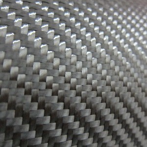
Figure 2: A typical twill weave where fibers directions are perpendicular resulting in longitudinal and transverse effects (https://www.rockwestcomposites.com).
Consider a titanium tube, with some practice you can weld it to other titanium tubes to make a structure. So long as the processing parameters during the drawing or rolling of that tube were consistent, there should be negligible difference from one tube to another. The exact same should be true for a composite tube, but in addition to the processing parameters, the layup of the material must also be consistent. This is where the anisotropy is beneficial; a top tube may have different layup than a down tube allowing for each portion of a frame to be uniquely suited to perform its job. However, this uniqueness can result in no two structures being the same even if they appear to be. In future posts, we will investigate the effects of these variations, how to identify them, and their impacts on the structures, as well as other interesting related topics.
References
- Silver, Nate. The Signal and the Noise: Why so Many Predictions Fail-but Some Don’t. New York: Penguin Press, 2012. Print.
- Reardon, Arthur C., ed. Metallurgy for the Non-metallurgist. ASM International, 2011. http://www.asminternational.org/documents/10192/3212401/05306G_Sample_BuyNow.pdf/ab60c086-2c71-4de0-91f6-aad1112cf4dc
- Roeseler, William G., et al. “Composite structures: the first 100 years.” 16th International Conference on Composite Materials. 2007. http://www.iccm-central.org/Proceedings/ICCM16proceedings/contents/pdf/MonA/MoAM1-01sp_roeselerw228184p.pdf
- Smith, James Ohrea. The effect of range of stress on the fatigue strength of metals. University of Illinois at Urbana Champaign, College of Engineering. Engineering Experiment Station., 1942.https://www.ideals.illinois.edu/bitstream/handle/2142/4540/engineeringexperv00000i00334_ocr.txt?sequence=2&isAllowed=y
- Baldwin, W. M. “Yield strength of metals as a function of grain size.” Acta Metallurgica 6.2 (1958): 139-141.
- Wilson, D. V., and J. A. Chapman. “Effects of preferred orientation on the grain size dependence of yield strength in metals.” Philosophical Magazine 8.93 (1963): 1543-1551.
- Yukitaka, Murakami, and Endo Masahiro. “Quantitative evaluation of fatigue strength of metals containing various small defects or cracks.” Engineering Fracture Mechanics 17.1 (1983): 1-15.
- Johnson, Gordon R., and William H. Cook. “Fracture characteristics of three metals subjected to various strains, strain rates, temperatures and pressures.” Engineering fracture mechanics 21.1 (1985): 31-48. http://isn-csm.mit.edu/literature/1985-efm-johnson.pdf
- Kobayashi, Hideo, and Hisahiro Onoue. “Brittle fracture of liberty ships.” Failure Knowledge Database 100 (1943): 67. http://www.sozogaku.com/fkd/en/hfen/HB1011020.pdf
- Poirier, P., Adrien Charpy, and A. Nicolas. Traité d’anatomie humaine: Les organes des sens. Masson et Cie., 1912.
- Griffith, Alan A. “The phenomena of rupture and flow in solids.” Philosophical transactions of the royal society of london. Series A, containing papers of a mathematical or physical character 221 (1921): 163-198. http://www.ewp.rpi.edu/hartford/~ernesto/Su2014/SMS/Readings/Griffith-RuptureandFlow1921-PhilTransRSocLond.pdf
- https://en.wikipedia.org/wiki/Benjamin_Bowden#The_Spacelander
- Tsai, Stephen W. Strength Characteristics of Composite Materials. Philco Corp Newport Beach CA, 1965. http://www.dtic.mil/dtic/tr/fulltext/u2/a307777.pdf
- Hart-Smith, L. J. “Expanding the capabilities of the Ten-Percent Rule for predicting the strength of fibre–polymer composites.” Composites Science and Technology 62.12 (2002): 1515-1544. http://s3.amazonaws.com/academia.edu.documents/33873710/ten_per_rule_hs2002.pdf?AWSAccessKeyId=AKIAIWOWYYGZ2Y53UL3A&Expires=1488640809&Signature=M9%2Fmc5T7fdCpa4JODMowruE1dgs%3D&response-content-disposition=inline%3B%20filename%3DTen_per_rule_hs2002.pdf